The Ultimate Guide To Sliding Rails For CubeSats: Engineering Safety And Mission Success
Introduction: Are Your CubeSat's Sliding Rails a Mission-Killer or a Launch-Pad?
Imagine spending years designing a groundbreaking CubeSat, only to have it fail because of a simple, overlooked component: the interface between your satellite and the launch vehicle. This isn't a hypothetical scenario; it's a persistent risk in the NewSpace industry. Sliding rails for CubeSats are far more than just metal strips; they are the critical, often unsung, mechanical link that determines whether your spacecraft reaches orbit or becomes expensive debris. They must be perfectly compatible with the dispenser, robust enough to survive launch vibrations, and precisely engineered to allow clean separation. This guide dives deep into the world of CubeSat sliding rails, moving beyond basic definitions to explore the engineering, standards, manufacturing, and safety practices that separate successful missions from catastrophic failures. Whether you're a first-time builder or a seasoned developer, understanding these foundational elements is non-negotiable for responsible spacecraft development.
The Critical Role of Sliding Rails in CubeSat Deployment
More Than Just a Track: The Primary Function of CubeSat Rails
At its core, a CubeSat sliding rail system serves two fundamental purposes: structural retention during the intense launch phase and predictable, clean deployment into orbit. These rails, mounted on the satellite's external frame, interface directly with the corresponding rails or tabs inside the launch dispenser (the P-POD or similar system). This interface must be friction-minimized to allow smooth ejection by a spring mechanism, yet secure enough to prevent any movement or rattling that could damage the satellite or the primary payload. A failure here can have cascading effects, potentially jeopardizing the entire launch manifest.
The High Stakes of Interface Failure
The consequences of a rail or dispenser failure are severe. As noted, failures of CubeSats, 6U dispensers, or interface hardware can damage the launch vehicle (LV) or a primary payload. This isn't just about losing one small satellite; it can put the entire CubeSat program in jeopardy, leading to increased insurance costs, launch provider reluctance, and reputational damage for the entire small satellite community. Therefore, developers must play an active role in ensuring safety by implementing rigorous engineering, testing, and verification for their rail systems.
Engineering and Design: The Foundation of a Reliable CubeSat
The SL CubeSat Structure: A Lightweight, Customizable Chassis
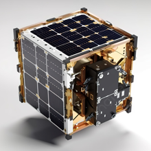
The journey to reliable sliding rails begins with the structure they are attached to. The SL CubeSat structure was developed as a lightweight chassis that can be the necessary foundation for even the most demanding missions. Constructed from advanced materials like 6061 aluminum, it provides an optimal strength-to-weight ratio. Crucially, this design philosophy acknowledges that one size does not fit all. If you still find a need to customize your structure—for unique payload dimensions, non-standard component layouts, or specialized thermal requirements—you always can, free of charge. This flexibility is key for research and technology demonstration missions that push the boundaries of the CubeSat form factor.
Engineering with Slide Rails on All Four Sides
A hallmark of professional CubeSat structures is the integration of slide rails on all four sides. This design, adhering to the widely accepted CalPoly CubeSat standards, is not arbitrary. Having rails on all four faces provides multiple, redundant interfaces. This allows the dispenser to engage the satellite from different orientations (though typically one pair is primary) and offers greater tolerance for minor manufacturing variations. It also simplifies ground handling and integration procedures, as technicians have more options for securing and maneuvering the satellite during pre-launch processing. These rails are not afterthoughts; they are engineered features integral to the structural frame.
Material Matters: Hard Anodized 6061 Aluminum
The choice of material for the rails themselves is critical. The best practices point to rails made of hard anodized 6061 aluminum. 6061 is a precipitation-hardened aluminum alloy known for its excellent mechanical properties and weldability. The hard anodization process creates a thick, protective ceramic-like oxide layer on the surface. This serves three vital functions:
- Corrosion Resistance: Protects against environmental degradation during storage and launch.
- Wear Resistance: Minimizes friction and wear against the dispenser's inner rails or tabs during launch vibration and the deployment stroke.
- Electrical Isolation: Prevents galvanic corrosion and provides a degree of electrical isolation between the satellite and the dispenser, which can be important for spacecraft charging management.
Design Heritage: Evolution from the IRIS Program
The design of these standardized rails is often "almost completely carried over from IRIS," though with some changes. The IRIS (International Releasable Interface Standard) initiative, led by The Aerospace Corporation, was a pivotal industry effort to standardize the mechanical and electrical interface between CubeSats and dispensers. By building on this proven heritage, manufacturers ensure a high level of compatibility and reliability. The "changes" typically involve minor refinements for manufacturability, updated material specifications, or adaptations for larger CubeSat form factors (like 6U, 12U, 16U) that weren't as prevalent when the original IRIS specs were drafted. This evolutionary approach balances innovation with the proven safety of established designs.
Manufacturing Excellence: From Prototype to Global Production
Mass Production Across the Full CubeSat Spectrum
The CubeSat revolution demands scalable solutions. We specialize in the mass production of CubeSat structures in various sizes, including 1U, 1.5U, 2U, 3U, 4U, 6U, 8U, 12U, and 16U. This breadth is crucial. While the 1U-3U sizes dominate university and small company projects, the larger formats (6U and above) are becoming the workhorses for serious science missions and commercial constellations due to their increased power, volume, and mass allowances. Mass production of these diverse sizes requires sophisticated CNC machining, fixturing, and quality control processes to ensure every unit—whether the first or the thousandth—meets identical specifications. This consistency is paramount for dispenser compatibility.
The Internal Frame: Securely Stacking PCBs
Beyond the external rails, the internal frame design is equally important. The internal frames are crafted to securely stack PCBs, allowing for easy attachment and detachment during assembly, integration, and testing (AIT). This is achieved through standardized standoff locations, threaded inserts, and card guide rails. A well-designed internal stack minimizes the need for custom brackets, reduces assembly time, and prevents stress on sensitive components from improper mounting. It directly contributes to the satellite's structural integrity and the ease with which engineers can access and modify subsystems.
The "Spare Flight" Model: A Benchmark for Efficiency
A compelling case study in efficient CubeSat development is the Spare Flight meet CubeSat requirements design cycle of 10 weeks and budget of $10,000 for a 1U CubeSat. This model demonstrates that with a standardized structure, pre-qualified components, and a streamlined process, a flight-worthy satellite can be produced rapidly and affordably. This "spare flight" or "pathfinder" approach is invaluable. It allows teams to build a non-flight unit for exhaustive mechanical testing—especially for rail/dispenser interface verification—without risking the primary flight hardware. The 10-week, $10k benchmark sets a realistic target for project planning and highlights the cost-effectiveness of using standardized, mass-produced structures.
Standards, Compatibility, and the Global Marketplace
Adhering to CalPoly CubeSat Standards
Compatibility is not accidental; it is by design. Our components are engineered with slide rails on all four sides, adhering to CalPoly CubeSat standards. The CalPoly (California Polytechnic State University) standards are the de facto industry norm for mechanical interfaces. They define the precise dimensions, tolerances, and surface finishes for the rails. By strictly adhering to these standards, a CubeSat structure guarantees it will physically interface with any dispenser that also follows the standard—which is virtually all reputable launch providers. This interoperability is the bedrock of the CubeSat launch ecosystem.
Ensuring Dispenser Compatibility: Rail vs. Tab Systems
To ensure safety and success of the mission, CubeSats will be compatible with either the rail system or the tab system dispensers by meeting the applicable requirements outlined in this document or the PSC website. This is a critical, nuanced point. There are two primary CubeSat dispenser interface types:
- Rail System: Uses long, continuous rails on the satellite that slide within corresponding rails in the dispenser (e.g., the common P-POD).
- Tab System: Uses small, protruding tabs on the satellite that engage with latches in the dispenser (e.g., some systems from ISISpace, NanoRacks).
A responsible manufacturer must ensure their structures can accommodate both, or clearly specify which system they are designed for. This involves precise control of rail height, width, and edge radii, or tab location and strength. Developers must consult the specific requirements of their chosen launch provider, often detailed on the PSC (PolySat/CubeSat) website or the provider's own integration manuals.
Navigating the Global Space Marketplace
For developers seeking dedicated launch solutions, the landscape is global. Discover a range of companies offering dedicated launch separation solutions for different satellite sizes on the global space marketplace. This includes not only the primary dispensers (like those from ESA, ULA, or commercial providers) but also companies that sell qualified, standalone rail systems or dispenser kits. When sourcing rails or structures, it's vital to verify that the supplier's products are flight-proven or at least rigorously tested to the relevant standards (e.g., ECSS, NASA GSFC-STD-5000B for vibration). The marketplace offers options, but due diligence is required to avoid counterfeit or non-compliant hardware.
Safety, Verification, and Best Practices
The Developer's Duty: Active Role in Safety
CubeSat developers should play an active role in ensuring the safety and success of CubeSat missions by implementing good engineering practice, testing, and verification of their systems. This cannot be overstated. You cannot simply buy a "compliant" structure and assume it will work. You must:
- Inspect: Perform incoming inspection on all rail hardware for damage, anodization quality, and dimensional conformance.
- Fit Check: Conduct a dry-fit with an actual dispenser or a qualified interface test fixture before final integration.
- Test: Subject your fully integrated satellite (or at least the rail interface section) to vibration testing that mimics the launch profile. This tests for rail loosening, structural resonance, and potential interference.
- Document: Maintain meticulous records of all inspections, fit checks, and test results. This documentation is often required by the launch provider for flight certification.
Building a Reference: A Guide for All Experience Levels
If you’ve been involved in the CubeSat world for a while, this guide will be a good reference for anything on which you might need a refresher. The field evolves, with new sizes (like 12U, 16U), new materials (like carbon fiber composites), and new dispenser designs. Even veterans need to revisit the fundamentals of mechanical interface standards, especially when branching into unfamiliar territory. This article serves as that refresher, consolidating core principles of rail design, compatibility, and safety into one resource.
Conclusion: Your Mission's Success Rides on These Rails
Sliding rails for CubeSats are the quintessential example of a "simple" component with profound mission implications. They are the mechanical handshake between your spacecraft and the rocket that carries it. From the lightweight, customizable SL CubeSat structure and the hard anodized 6061 aluminum rails engineered to CalPoly standards, to the realities of mass production across 1U to 16U sizes and the imperative of rigorous testing, every detail matters. The 10-week, $10k "spare flight" model proves that quality and speed can coexist, while the existence of both rail and tab dispenser systems on the global marketplace means developers must be vigilant about specific compatibility requirements.
Ultimately, the active role of the developer in verification is the final, indispensable line of defense against failure. By respecting the heritage of designs like those from the IRIS program, by understanding that failures can jeopardize the entire CubeSat program, and by prioritizing the secure stacking of internal PCBs, you build more than a satellite—you build trust. Trust with launch providers, with co-passengers, and with the sustainability of the small satellite revolution. Your CubeSat's journey to orbit begins and ends with the integrity of its sliding rails. Engineer them with the utmost care.