Gen 3 Tuning: What Is Good Data And How To Use It Effectively
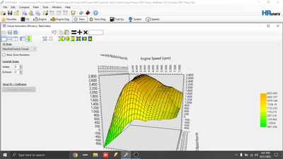
What Exactly Constitutes "Good Data" in Gen 3 Tuning?
You've likely heard the phrase "garbage in, garbage out" in the world of computing. In the realm of high-performance engine management, this axiom is doubly true. When it comes to Gen 3 tuning, the single most critical factor separating a successful, safe, and powerful tune from a potentially destructive one is the quality of the data you collect and interpret. But what does "good data" actually mean? Is it just a log file with a lot of numbers? Far from it. Good data in the context of a GM Gen 3 LS engine is accurate, relevant, contextual, and actionable information that directly informs the precise adjustments needed to the Volumetric Efficiency (VE) tables, fuel maps, and other parameters within the Power Control Module (PCM). It’s the difference between guessing and knowing. This comprehensive guide will dismantle the mystery, walking you through the complete process of tuning Gen 3 VE tables using short-term fuel trims, from foundational setup to advanced boost scaling, all built on a bedrock of reliable data.
Foundational Prerequisites: You Cannot Tune What You Cannot Measure
Before you even open HP Tuners or VCM Scanner, you must accept a non-negotiable truth: a wideband O2 sensor is required for the tuning described in these procedures. The stock narrowband sensor is a simple on/off switch for the catalytic converter. It tells the PCM if the mixture is slightly rich or lean, but not how much. A wideband, or air-fuel ratio (AFR) sensor, provides a precise, real-time numerical value (e.g., 14.7:1 for stoichiometric, 12.5:1 for full power). This is your primary feedback mechanism. Without it, you are tuning blind, relying on the PCM's own potentially flawed interpretations via fuel trims. Invest in a quality, fast-responding wideband controller and sensor, and ensure its reading is verified and accurate before proceeding. Calibration is key; an uncalibrated wideband will teach your PCM the wrong lessons.
Equally critical is addressing your fuel injector data. If you have upgraded your fuel injectors, the injector data must be set correctly before you start. The PCM uses the injector flow rate (in lb/hr or cc/min) and the injector slope (a constant in the calibration) to calculate how long to open the injector (pulse width) to deliver the required fuel. If you tell the PCM your new 42 lb/hr injectors are still the stock 28 lb/hr units, the PCM will open them 50% longer than necessary for a given target AFR, leading to a dangerously rich condition. This step is not optional; it is the first and most fundamental piece of data integrity. Enter the correct injector flow rate and slope in HP Tuners under Edit > Injector Flow Rate and ensure the Injector Slope constant matches your injector type (often a value like 26.5 for high-impedance, 50+ for low-impedance). Only with a correct baseline can the subsequent fuel trim data be meaningful.
Decoding the Language of the PCM: Fuel Trims
The PCM is constantly adjusting fuel delivery to hit its target AFR. It does this via fuel trims. Understanding the difference between Short-Term Fuel Trim (STFT) and Long-Term Fuel Trim (LTFT) is paramount for effective data interpretation.
- STFT (Short-Term Fuel Trim): This is the PCM's immediate, reactive correction. It responds in real-time to the oxygen sensor's feedback, making rapid, small adjustments (positive for adding fuel, negative for removing fuel). STFT is highly volatile and changes with every acceleration, deceleration, and load change. It's a great indicator of momentary AFR errors but is too noisy for direct table tuning.
- LTFT (Long-Term Fuel Trim): This is the PCM's learned, adaptive correction. It averages the STFT over time under steady-state conditions (typically cruise or light load) and stores this value. LTFT represents the PCM's cumulative assessment of a systematic error in the fuel model—primarily the VE table and MAF transfer function. A consistent positive LTFT (+10% or higher) means the PCM is consistently adding fuel because the model thinks there's more air than there actually is, or it's not injecting enough fuel for the measured air. A consistent negative LTFT means the opposite.
In tuning part throttle we will tweak the maf transfer function according to the ltft values we logged. This is the core of the process. During light-load, steady-state cruising (e.g., 50 mph on a flat road), the engine is in Closed Loop mode, targeting a stoichiometric AFR (~14.7:1). If your wideband reads 15.2:1 (lean), the PCM will see this via the O2 sensor and apply a positive LTFT (e.g., +8%) to add fuel. This +8% LTFT is your data. It tells you: "The airmass the PCM thinks it's seeing (from the MAF) is 8% higher than the actual airmass entering the cylinders, or my fuel delivery is 8% low." Since we've already verified injector data, the error points squarely at the MAF transfer function (the table that converts MAF voltage/hz to grams/sec of air) or the VE table at that specific RPM/load point. For part-throttle, the MAF is the primary airmeter, so we adjust the MAF curve first to bring LTFTs as close to zero as possible across the board.
The Complete Process: Tuning Gen 3 VE Tables from Start to Finish
This allows you to not only know exactly what the PCM is thinking but also what to change to get the desired results. Here is the logical, iterative workflow:
- Preparation & Baseline: Ensure the engine is at operating temperature, in good mechanical health, and has the correct injector data and base calibration loaded. Connect your wideband and ensure its output is logged (either via a serial cable to a laptop or a compatible wideband that logs to HP Tuners). This document provides instructions for tuning a gen iii vehicle using hp tuners software with a wideband o2 sensor. It emphasizes reading help files and documentation to understand the software before starting. Know how to log parameters (MAF, STFT, LTFT, RPM, TPS, AFR) and how to edit tables.
- Data Logging (The "What"): We explore what’s possible with logging in vcm scanner software and how to read data logs. Perform a series of steady-state cruises. Find a flat, safe stretch of road. Hold a constant speed (e.g., 45, 55, 65 mph) for 30-60 seconds each, allowing LTFTs to stabilize. Log all relevant parameters. You are looking for stable LTFT values at each steady-state point. Ignore data during acceleration or deceleration.
- Data Analysis (The "So What"): Review your logs. Plot LTFT vs. RPM or vs. MAF frequency. You will see a trend. Perhaps LTFT is +5% at low RPM/MAF and +12% at higher RPM/MAF. This tells you the MAF curve is under-reporting airmass (PCM thinks there's more air than there is, so it adds fuel via LTFT). To correct, you must increase the MAF value in the transfer function at those corresponding frequencies. Conversely, a negative LTFT means the MAF is over-reporting, and you must decrease the value.
- MAF Transfer Function Adjustment: In HP Tuners, go to Edit > MAF Transfer Function. This is a 1D table of MAF Hz (or voltage) vs. Airflow (g/s). Using your LTFT data, calculate the correction factor. If your LTFT is +10% at a specific Hz, increase the g/s value in the MAF table at that Hz by approximately 10%. Make small, conservative changes (2-5% at a time). Save, flash, and repeat the logging process. Your goal is to have LTFTs oscillate around 0% (±2-3%) across the entire part-throttle, steady-state MAF range.
- VE Table Adjustment (WOT/Transient): Once MAF is dialed in for part-throttle, you move to Wide-Open Throttle (WOT) tuning, where the MAF is less critical for the PCM's primary fuel calculation in Gen 3s (it uses a speed-density model based on MAP, IAT, and VE). Here, you use wideband AFR data directly and Short-Term Fuel Trims (STFT). Perform WOT pulls in each gear, logging AFR, STFT, RPM, and load (Manifold Pressure). If AFR is lean (e.g., 12.0:1 on a 11.5:1 target) and STFT is positive (adding fuel), your VE table is too low at that RPM/load point. You must increase the VE percentage. If AFR is rich and STFT is negative, decrease VE. Adjust the 2D VE table (RPM vs. MAP) in small increments (1-2% per cell), one cell or row at a time, and retest. This is the iterative "pull, log, adjust, repeat" cycle.
Scaling for Boost: Learning How to Scale 0411 Gen 3 LS ECMs
The process above is for naturally aspirated (NA) engines. For forced induction (turbo or supercharger), the challenge magnifies. Learning how to scale 0411 gen 3 ls ecms for boost involves understanding that the stock PCM's speed-density model (VE table) is calibrated for atmospheric pressure. Boost pressure skews the MAP sensor reading. You must adjust the MAP sensor calibration (if using a different sensor) and, more importantly, scale the VE table for pressure. The VE table values are for a 1-bar (atmospheric) environment. Under 10 PSI of boost, the absolute pressure is ~1.68 bar. The PCM doesn't inherently know this; it sees a higher MAP voltage and, without correction, will think the engine is under much higher load than it is, leading to a lean condition.
The solution is to use the Pressure Correction factor or adjust the VE table values by the pressure ratio. A common method is to multiply the target VE value by (Absolute Pressure / 1). For 10 PSI boost (1.68 bar abs), you might need to increase the VE values in the boosted regions by ~68%. This is a coarse starting point; fine-tuning with wideband AFR data under boost is still essential. This is an advanced step where good data—accurate, real-time boost pressure and AFR logging—is absolutely critical to avoid engine-destroying lean conditions.
The Ecosystem: Where to Find Knowledge and Community
The GM LS platform is one of the most popular engines of this generation, which is a massive advantage for tuners. You can pretty much find out anything you want to know about these engines from forums, facebook groups and youtube. Sites like LS1Tech, Team Chevelle, and specific Facebook groups for HP Tuners or specific ECM models (P01, 0411) are invaluable. Search for your specific vehicle, ECM code, and issue. Chances are, someone has logged the same data, faced the same LTFT trends, and shared their MAF/VE corrections. However, treat all community data as a starting point. Your specific engine's build, sensor calibrations, and even atmospheric conditions will create unique data. Use community knowledge to understand principles and common pitfalls, but rely on your own wideband logs for the final, authoritative adjustments.
Understanding the Broader Context: Gains and Realistic Expectations
A common question is about typical gains on turbocharged petrol and diesel engines. For a well-tuned Gen 3 LS in a lightweight car, gains of 50-100+ horsepower over a stock, safe tune are very achievable with proper boost levels (8-12 PSI). For diesel platforms (like the Duramax, which also uses advanced ECMs), the gains and tuning methodology differ significantly, focusing more on rail pressure and timing, but the principle of using good data (exhaust gas temperature, rail pressure, fuel quantity) remains identical. The key takeaway is that the largest gains often come from simply correcting the factory's conservative fuel and spark curves and optimizing the VE/MAF tables for your specific engine's breathing characteristics. A perfect MAF curve alone can recover 10-15 horsepower and significantly improve drivability and fuel economy.
The Critical Mindset: From Data to Decisions
Sam how to tune using hptuners! is a common plea. The software is just a tool. The skill lies in interpreting the data stream. Your wideband is your truth-teller. Your fuel trims are the PCM's complaints. Your job is to reconcile them. When you see a +15% LTFT at 2500 RPM, you don't just "add fuel." You think: "At 2500 RPM and X g/s of airflow, the PCM is consistently adding 15% fuel. My MAF value at X Hz is therefore 15% too low. I will increase the MAF table value at X Hz by 15%." This precise, cause-and-effect thinking is what separates a tuner from a button-pusher. Always make one change at a time, verify its effect with new logs, and proceed methodically.
Conclusion: Good Data Is the Only Data That Matters
Tuning a Gen 3 LS engine is not an arcane art; it is a disciplined science of data acquisition and analysis. Good data—defined by a calibrated wideband sensor, correct injector parameters, and methodical logging of fuel trims and airmass—empowers you to see past the PCM's black box. It transforms the tuning process from a gamble into an engineering exercise. By following the structured approach of stabilizing part-throttle LTFTs via MAF adjustment, then fine-tuning WOT VE tables with wideband AFR and STFT guidance, you can achieve a tune that is not only powerful but also safe, efficient, and reliable. Remember to scale appropriately for boost, leverage the vast community knowledge of the GM LS platform, and always prioritize understanding over rote memorization of table values. The world’s leading publication for data science, data analytics, data engineering, machine learning, and artificial intelligence professionals might focus on big data, but for the internal combustion engine, the most important data is the specific, real-time feedback from your own machine. Listen to what it tells you, and you will unlock its true potential.